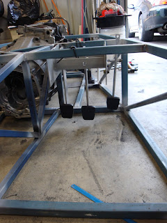
The floor used is as recommened by FMS, 1.6mm Zincaneal; it was folded with the reinforcing ribs as detailed in the FMS plans, tack welded in place and then back stitch welded to prevent buckling of the sheetmetal.
The rib ends were trimmed and bent at about 45 degrees and welded smooth to allow the floor to slide over anything it grounds on rather that abruptly stopping/catching on an exposed lip.
A low speed fan nearby minimised me inhaling any of the nasty fumes the zinc gives off which would otherwise make me pretty sick!
Onto the steering rack and/or diff next.
Wednesday, December 2, 2009
Front Suspension
Donor front suspension as used on JZA80 Supra and JZZ30/UZZ30 Soarer
A jig was made of the donor Soarer/Supra front crossmembers.
Forward lower and upper front suspension mounts were fabricated froms scratch as the front OEM crossmember is made of alluminium and was not suitable to fit to the frame.
Rear lower front suspension mount was utilised from the steel OEM rearmost front lower crossmember.
The jig was them offered up to the frame and the fabricated mounts tack welded in the correct position.
Once tacked into position, round tube was utilised to reinforce these hard suspension points.
I'm pleased with my progress having taken less than 3 months to reach the stage of a rolling chassis - now to maintain the momentum...
Tuesday, November 17, 2009
IRS Rear suspension
Friday, October 30, 2009
1ZZ FE engine to J160 gearbox adapter
I've spent a busy few weeks fabricating the adapter between the engine and gearbox.
I started off with a 16mm 400x400mm alloy plate as well a 4mm 400x400 transparent polycarbonate template and milled out the 76mm centres to locate the crankshaft accurately as the reference.
I carefully drilled out each hole for the engine and gearbox bolts and dowells on the clear template and them transposed them on the alloy plate.
I had a pair of helicoils tapped/fitted in the plate for the starter motor bolts as I made provision for the starter to be bolted to the plate rather than the plate to the starter - this will allow future removal of the starter without having to remove the egine/gearbox and seperating the engine/gearbox just to be able to access the OEM bolts.
A lot of counter sinking holes and tracking down suitable bolts/nuts to hold the combination together.
After everything was test fitted, the plate was trimmed down and linished to the adapter ring as pictured.
Sunday, October 11, 2009
Engine mounts and start on pedal and seat position
Engine and bellhousing positions have been roughly set - would have been nice for the engine to sit a little further back and a little lower but this seems to be the best compromise for footwell packaging and sump longevity.
Note the ~12 degree lean of the 1ZZ as a result of the OEM sump/pickup design.
The 1ZZ has no provision for engine mounts when used in a north south position, so after much consideration I settled on the design below which attempts to spread the load over a number of different bolt mounting bosses on different planes.
I also made a start on fixing the seat mount position relative to the pedal position.
Seats are Whitepointer ADR compliant seats covered in marine grade vinyl running on MX5 rails.
Pedal box is a modified Arrow assembly.
Saturday, September 26, 2009
Basic chassis construction complete
Another big day on the MIG - I finished tack welding all the rear (C1) chassis together and I then started final welding the rest of the chassis moving around regularly to minimise distortion from excessive heat build up.
I ground back all the welds where sheetmetal needs to be attached in the future and sprayed primer in the weld areas to minimise surface rust whilst the chassis is worked on in coming months prior to the final painting.
Subscribe to:
Posts (Atom)